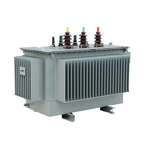
S11-M S9-M Series Oil-immersed Hermetically-sealed Transformers
PRODUCT OVERVIEW
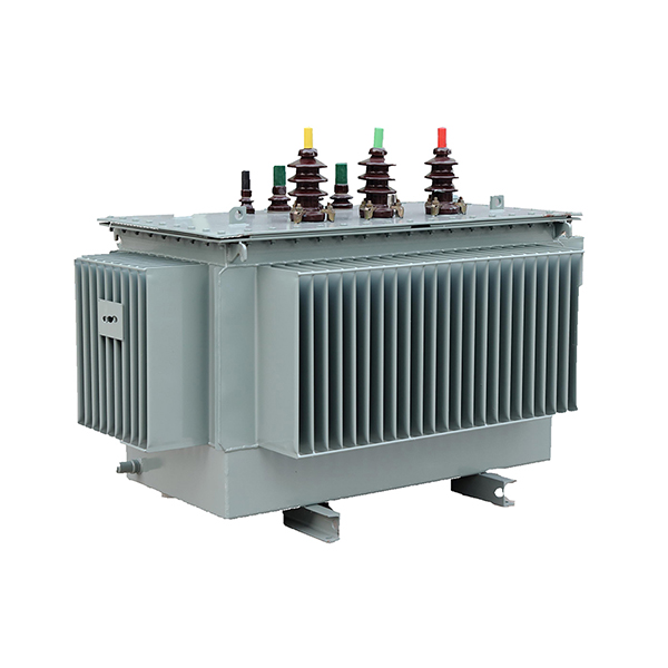
The Hermetically-sealed transformer is the transformer of which inner tank is totally isolated from the outside atmosphere. Its volume changes with shrinkage and expansion of the corrugated tank sides. Moisture and oxygen can not enter the tank from outside, thus slowing down the aging of the insulating material It doesn't need core-lifting check before operation or maintenance after putting into operation, which greaily improves the reliability of transformer.
It adopts PCCAD as its design software, and meets IEC60076, GB1094 standard, and has passed the IS09001 quality system certification. The coil, wound by high intensiry enameled wire (or paper wrapped) with cylinder (or disc) structure and Ampere-Turn balance, reasonable insulation structure have a good short-circuit withstand capacity. The fastening parts are locknuts.
Even after long-distance transportation, they are not loose. All sealing material is made of high quality acrylic rubbery which can effectively prevent against light-aging, electricity aging and heat aging. It is equipped with "remote sensor" signal thermometer and pressure relief valves to enhance the reliability of transformers.
MAIN FUNCTIONS AND CHARACTERS
Without such device like conservator and air breather, it ensures that the transformer oil is not iri contact with air. So commonly, the transformers can be used continuously for 20 years without any particular treatment.
Excellent rubber is adopted in the sealing parts.
Vacuum oil-filing process is used.
RANGE OF APPLICATION
It can be widely used in urban power network as well as petrochemical, metallurgical, textile and humid, inaccessible enterpnses, and mining.
S9-M Series Three-phase Double-winding Distribution Transformers with Off-circuit Tap Changer
| Rated capacity(kVA) | Voltage ratio(kV) | Connection Symbol | Loss(W) | No-load current(%) | lmpedance(%) | Weight(kg) | Outline Dimension(mm) | Gauge(mm) | |||||
| H.V | L.V | No-load Loss | Full-load Loss | Oil weight | Total Weight | L | W | H | |||||
| 30 |
6 6.3 10 10.5 11 ±5% or ±2 x2.5% |
0.4 |
Yyn0 Dyn11 |
130 | 600 | 2.1 | 4 | 70 | 295 | 835 | 555 | 915 | 400x400 |
| 50 | 170 | 870 | 2.0 | 85 | 390 | 890 | 630 | 945 | 400x400 | ||||
| 63 | 200 | 1040 | 1.9 | 90 | 430 | 860 | 720 | 980 | 400x400 | ||||
| 80 | 240 | 1250 | 1.9 | 115 | 500 | 890 | 730 | 1015 | 400x400 | ||||
| 100 | 290 | 1500 | 1.8 | 120 | 555 | 910 | 740 | 1030 | 400x400 | ||||
| 125 | 340 | 1800 | 1.7 | 130 | 660 | 935 | 740 | 1090 | 550x550 | ||||
| 160 | 400 | 2200 | 1.6 | 155 | 780 | 970 | 745 | 1135 | 550x550 | ||||
| 200 | 480 | 2600 | 1.5 | 175 | 900 | 1005 | 795 | 1185 | 550x550 | ||||
| 250 | 560 | 3050 | 1.4 | 200 | 1060 | 1040 | 830 | 1210 | 550x550 | ||||
| 315 | 670 | 3650 | 1.4 | 230 | 1240 | 1430 | 840 | 1280 | 550x550 | ||||
| 400 | 800 | 4300 | 1.3 | 265 | 1440 | 1470 | 860 | 1325 | 660x660 | ||||
| 500 | 960 | 5100 | 1.2 | 305 | 1740 | 1550 | 900 | 1430 | 660x660 | ||||
| 630 | 1200 | 6200 | 1.1 | 4.5 | 410 | 2180 | 1665 | 940 | 1480 | 660x660 | |||
| 800 | 1400 | 7500 | 1.0 | 470 | 2560 | 1750 | 1005 | 1560 | 820x820 | ||||
| 1000 | 1700 | 10300 | 1.0 | 470 | 2745 | 1785 | 1025 | 1715 | 820x820 | ||||
| 1250 | 1950 | 12000 | 0.9 | 600 | 3540 | 1970 | 1170 | 1745 | 820x820 | ||||
| 1600 | 2400 | 14500 | 0.8 | 660 | 4160 | 2015 | 1190 | 1810 | 820x820 | ||||
S11-M series three-phase double-winding distribution transformers with off-circuit tap changer
| Rated capacity(kVA) | Voltage ratio(kV) | Connection Symbol | Loss(W) | No-load current(%) | lmpedance(%) | Weight(kg) | Outline Dimension(mm) | Gauge(mm) | |||||
| H.V | L.V | No-load Loss | Full-load Loss | Oil weight | Total Weight | L | W | H | |||||
| 30 |
6 6.3 10 10.5 11 ±5% or ±2 x2.5% |
0.4 |
Yyn0 Dyn11 |
100 | 630/600 | 2.3 | 4 | 60 | 265 | 750 | 560 | 870 | 400x400 |
| 50 | 130 | 910/870 | 2 | 85 | 350 | 780 | 560 | 880 | 400x400 | ||||
| 63 | 150 | 1090/1040 | 1.9 | 95 | 410 | 800 | 570 | 910 | 400x400 | ||||
| 80 | 180 | 1310/1250 | 1.9 | 100 | 460 | 820 | 580 | 940 | 400x400 | ||||
| 100 | 200 | 1580/1500 | 1.8 | 110 | 515 | 860 | 600 | 960 | 400x400 | ||||
| 125 | 240 | 1890/1800 | 1.7 | 120 | 600 | 880 | 650 | 1040 | 550x550 | ||||
| 160 | 280 | 2310/2200 | 1.6 | 130 | 660 | 900 | 700 | 1100 | 550x550 | ||||
| 200 | 340 | 2730/2600 | 1.5 | 150 | 770 | 1070 | 730 | 1150 | 550x550 | ||||
| 250 | 400 | 3200/3050 | 1.4 | 175 | 905 | 1170 | 780 | 1170 | 550x550 | ||||
| 315 | 480 | 3830/3650 | 1.4 | 200 | 1030 | 1320 | 840 | 1190 | 550x550 | ||||
| 400 | 570 | 4520/4300 | 1.3 | 225 | 1235 | 1360 | 870 | 1220 | 660x660 | ||||
| 500 | 680 | 5410/5150 | 1.2 | 280 | 1470 | 1480 | 950 | 1250 | 660x660 | ||||
| 630 | 810 | 6200 | 1.1 | 4.5 | 325 | 1805 | 1560 | 990 | 1290 | 660x660 | |||
| 800 | 980 | 7500 | 1 | 370 | 2120 | 1660 | 1070 | 1350 | 820x820 | ||||
| 1000 | 1150 | 10300 | 1 | 470 | 2390 | 1730 | 1150 | 1480 | 820x820 | ||||
| 1250 | 1360 | 12000 | 0.9 | 520 | 2900 | 1850 | 1350 | 1550 | 820x820 | ||||
| 1600 | 1640 | 14500 | 0.8 | 610 | 3600 | 2000 | 1400 | 1600 | 820x820 | ||||
Note:For transformers with the capacity of 50OkVAand below,values of load loss above the slash of the table apply to Dyoll connection,and values of load loss below the slash apply to Yyn0 connection.

