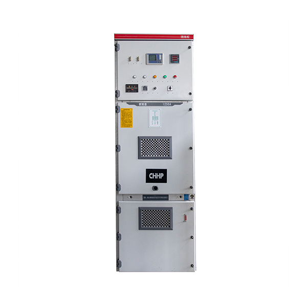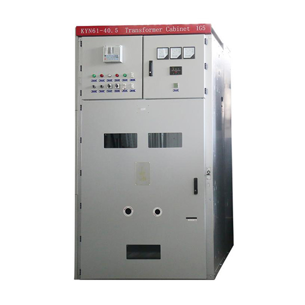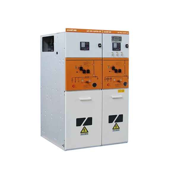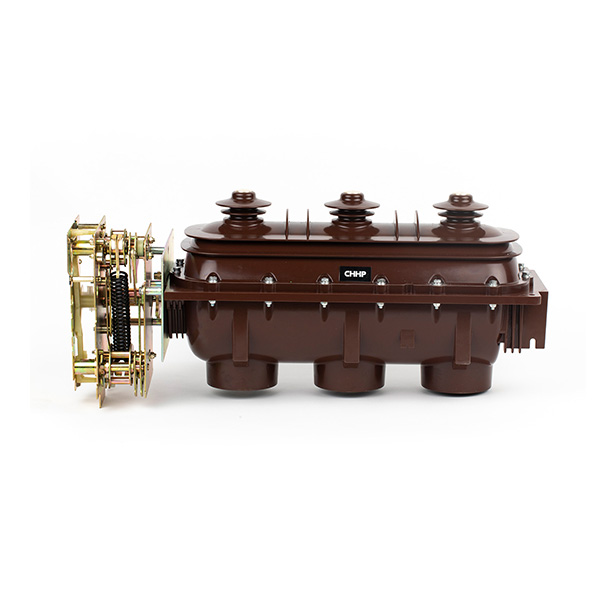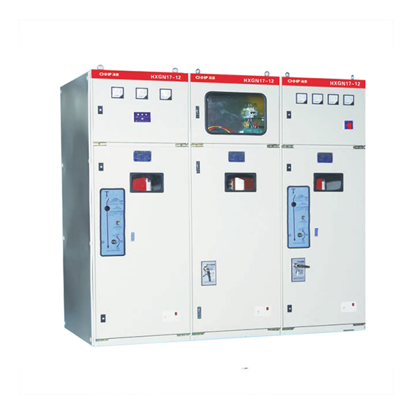
HP-SRM-12/24/33 GAS Insulated Metal-enclosed Combined Electrical Switchgear
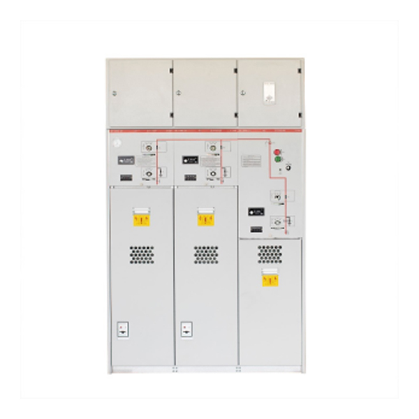
HP-SRM-12/24 series of ring main unit is SF6 gas-insulated metal common tank enclosed switchgear, consisting of load break switch unit, load break switch fuse combination electrical unit, vacuum circuit breaker unit, and the incoming line unit of bus. It adopts a range of advanced technologies and materials, with excellent electrical and mechanical properties, less affected by environment and climate, in small size, easy to install, easy to operate, with no need of maintenance, and can be flexibly combined. Its clear and intuitive design ensures simple and direct operation, the feeder's connection capacity is large, suitable for a variety of wiring systems.
Unit Definition
| Unit code | Meaning |
| C | Standard single casing load break switch unit |
| F | Load break switch and fuse combination |
| V | Apparatus unit |
| D | Cable unit(without switch) |
| + | Side casing of busbar |
| - | Top casing of busbar |
| SL | Bus couple unit |
| M | Metering unit |
| PT | PT unit |
| 1K2(4) | Double-sleeve outgoing load break switch unit |
Technical Specification
|
Item |
Unit |
Load break switch unit |
Combination apparatus |
Fuse unit |
|
|
Rated voltage |
kV |
12/24/33 |
12/24/33 |
12/24/33 |
|
|
Rated frequency |
Hz |
50 |
50 |
50 |
|
|
Rated current |
A |
630 |
Depend on rated current of fuse |
630 |
|
|
P.F.withstand voltage( phase to phase,phase to earth ) |
|
42/65/95 |
42/65/95 |
42/65/95 |
|
|
Ated insulation levels |
P.F.withstand voltage(Across open contacts) |
kV - |
48/79/118 |
48/79/118 |
48/79/118 |
|
Lightning impulse withstand voltage( phase to phase,phase to earth) |
|
2/2 |
2/2 |
2/2 |
|
|
Lightning impulse withstand voltage( phase to phase,phase to earth) |
|
75/125/185 |
75/125/185 |
75/125/185 |
|
|
Across open contacts |
|
85/145/215 |
85/145/215 |
85/145/215 |
|
|
Ogauge pressure test |
|
Pass |
Pass |
Pass |
|
|
Rated short time withstand current |
kA |
20/4s/20/3s |
- |
20/4s/20/3s |
|
|
Rated peak withstand current |
kA |
63 |
-- |
63 |
|
|
Rated short circuit making current |
kA |
50 or 63 |
Subject to high-voltage fuse |
50 |
|
|
Rated short circuit breaking current |
kA |
- |
Subject to high-voltage fuse |
20/20 |
|
|
Rated transform current |
A |
- |
1750/1400 |
- |
|
|
Rated active load breaking current |
A |
630 |
- |
- |
|
|
Rated Closed loop breaking current |
A |
630 |
- |
63 |
|
|
Mechanical life |
Load break switch/breaker |
Time |
5000 |
5000 |
10000 |
|
lsolating switch/earthing switch |
|
5000 |
5000 |
5000 |
|
|
Loop resistance |
μΩ |
≤120 |
- |
≤120 |
|
|
Lnflation pressure |
Rated inflation pressure(absolute pressure) |
Bar |
1.3/1.4 |
1.3/1.4 |
1.3/1.4 |
|
Minimum inflation pressure(absolute pressure) |
|
1.2 |
1.2 |
1.2 |
|
|
Relative rate leakage of gas |
% |
≤0.02/0.05 |
≤0.02/0.05 |
≤0.02/0.05 |
|
Remark: 1.Neutral point earthing system through low resistance
2 :Neutral point earthing/non-earthing system through arc suppression coil
Other Data
| Normal ambient conditions | Sfe pressure | 0.4bar, below 20℃ |
| Ambient temperature | Leakage rate per year | <0.25%/year |
| Maximum temperature +50℃ | Protection degree | |
| 24hours average +35℃ | SF6gas chamber | IP67 |
| Minimum temperature -40℃ | Switchgear cover | IP67 |
| Humidity | ||
| Maximum relative | ||
| Average humidity |
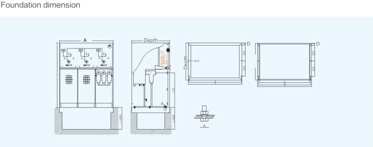
Switch Structure And Size
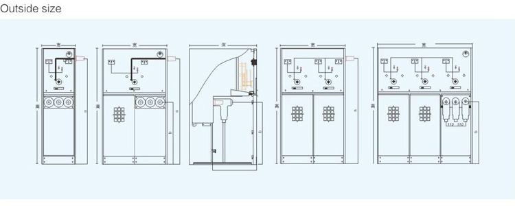
Unit:mm
| Model | Width | Depth | Height | a | b | c | Weight |
| C+ | 371 | 751 | 1336 | 1146 | 710 | 510 | 136 |
| 1K2(4) | 426 | 820 | 480 | 420 | 420 | 510 | 182 |
| 2C+ | 696 | 751 | 1336 | 1146 | 710 | 510 | 206 |
| 3C | 1021 | 751 | 1336 | 1146 | 710 | 510 | 300 |
| 4C | 1346 | 751 | 1336 | 1146 | 710 | 510 | 390 |
| 5C | 1671 | 751 | 1336 | 1146 | 710 | 510 | 486 |
| F | 371 | 751 | 1336 | 1146 | 710 | 510 | 164 |
| V | 371 | 751 | 1336 | 1146 | 710 | 460 | 230 |
Remarks:All above is only for reference(please refer to Technology Department for 20kv switchgear parameter)
